
Since I’m a software developer, I’ve always been wanting to do some hardware stuff (including some soldering) with my Raspberry Pi. So, for starters, I picked something that was useful and only involved sensors (no actors - yet):
Measuring temperatures at home.
Neither rocket science nor cool IoT “coffe is ready when I get out of the shower in the morning”, I know.
The sensor(s) should send a signal once an hour, without cable, and run on battery.
As the whole IoT thing is still relatively new, there are no standards yet. I picked the product line from Ciseco (currently being rebranded to Wireless Things (www.wirelessthings.com)). Affordable and good documentation. And, more important: These people are passionate about their product!
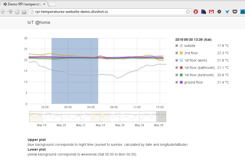
Before we get started here is a quick preview of what we want to accomplish (for details about the UI see part3): http://rpi-temperatures-website-demo.firebaseapp.com/
So let’s get started:
- 2 battery powered sensors transmitting temperature data once per hour via radio frequency.
- Raspberry Pi is powered 24/7 and records signals from sensors.
Parts & Costs
- 1x £3.90 Slice of Pi http://shop.ciseco.co.uk/slice-of-pi-add-on-for-raspberry-pi/
- 2x £8.50 Sensor THERMISTOR http://shop.ciseco.co.uk/temperature-xrf-development-sensor-thermistor/
- 3x £11.88 XRF wireless RF radio UART serial data module http://shop.ciseco.co.uk/xrf-wireless-rf-radio-uart-serial-data-module-xbee-shaped/
Total: £56.54
If you only want a single sensor (1 Slice of Pi, 1 Sensor, 2 XRF modules): £36.16
Setup overview
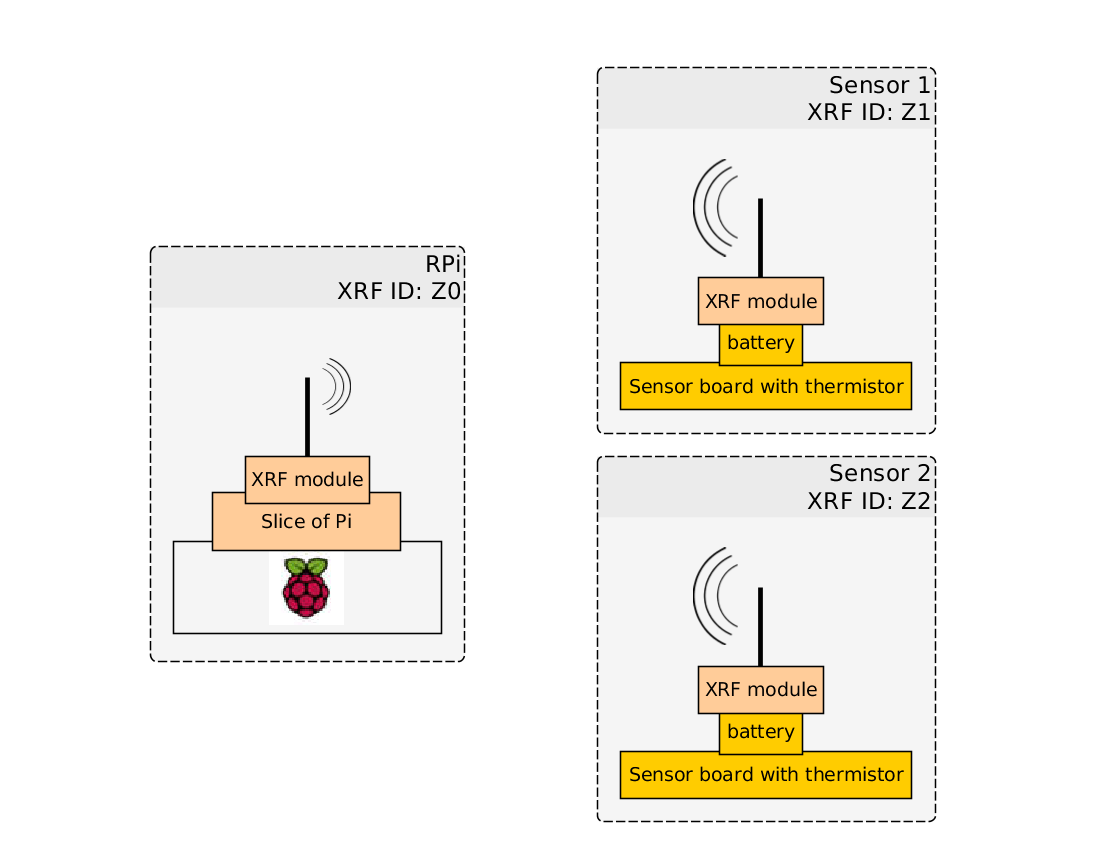
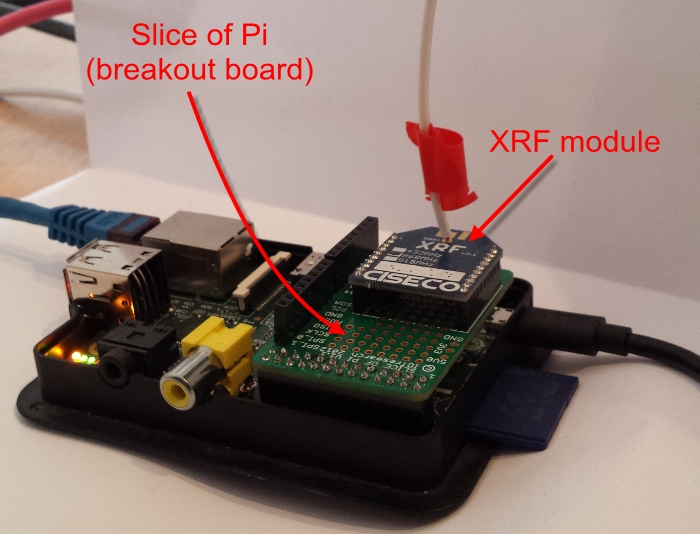
- On the left is the Raspberry Pi with an XRF module mounted to the Slice of Pi.
- The Slice of Pi acts as a breakout board.
- The XRF module will receive data.
- The Raspberry Pi will be continously monitoring input and storing the information locally to an SQLite3 database. See [part 2]((/blog/2015/07/10/remotly-measuring-temperatures-with-a-raspberry-pi-using-radio-frequency-modules-from-ciseco-part-2-software/) for details.
- On the right are two sensors with XRF modules.
- These modules will send temperature data once per hour to the Raspberry Pi.
- These modules run on battery power.
- You can have as many of these sensors as you want.
Each XRF module requires a unique id (‘XRF ID’ in the image above).
Hardware: Fitting the pieces & soldering
The official documentation is pretty good. If you know what you’re doing.
- For the Slice of Pi: http://openmicros.org/GSG/Slice%20of%20Pi%20-%20v1-1%20getting%20started%20guide.pdf
- For the sensor module(s): http://openmicros.org/index.php/articles/88-ciseco-product-documentation/211-ccb-coin-cell-board-pictorial-build-guide
In case you are not really sure what you are doing with the soldering iron: Keep calm. There is a lot of information on the internet. I found the following step-by-step instruction useful:
Raspberry Pi - Assemble your temperature THERMISTOR with an XRF transmitter probe
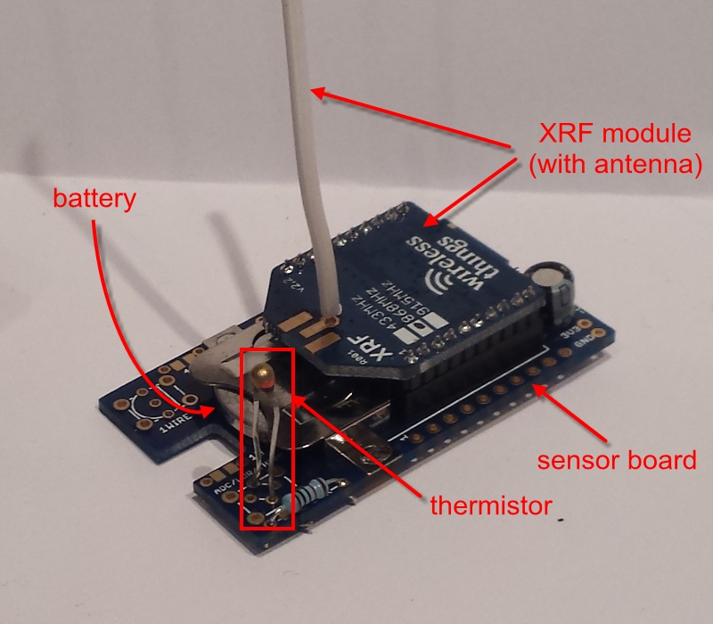
Here is what the assembled sensor looks like:
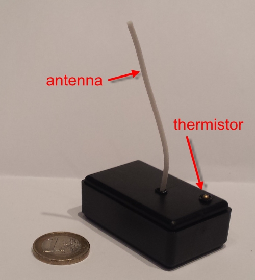
Here is a picture of the sensor in the box. You have to create the holes in the top of the box yourself. I just used the soldering iron to melt both holes, which is probably not considered best practice ;-)
And here is a picture of the Raspberry Pi with an XRF module mounted on the Slice of Pi:
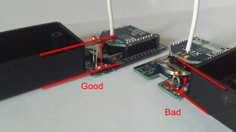
Note: The sensor comes with a box. In case you want to place the sensor inside the box make sure not to solder the thermistor to close to the board. You will want to make a hole in the box and have the thermistor stick out. Otherwise the thermistor will be inside the closed box and measure the temperature inside the box (instead of outside the box). Here is a picture illustrating the issue:
OS
This is one of the reasons I picked Ciseco for my simple project: They provide a standard Linux distribution (Raspbian) including their drivers.
This means the “Slice of Pi” works out of the box.
And the rest of the system behaves like a normal Raspbian system. There is no vendor “lock-in”.
Ciseco’s patched version of Raspbian here. Currently this is http://openmicros.org/Download/2015-05-05-raspbain-wheezy-raswik-shrunk.img.zip. I used the slightly older version http://openmicros.org/Download/2014-12-24-wheezy-raspbian-ciseco-shrunk.img.zip.
Software (well, actually Firmware)
All parts are soldered and the RPi has the correct operating system.
Our next steps (from a bird’s eye perspective) are:
- uploading the correct firmware onto the sensors' XRF module
- configuring the sensors' XRF module
The following instructions are mostly taken from Sean Landsman’s excellent tutorial.
Upload firmware to sensor(s)' XRF module
Why do we have to do this?
The sensor board is generic and can be configured for working with different types of sensors. We’re using a thermistor, in case you forgot… The thing with the antenna is the XRF module. We have 3 XRF modules: 1 for receiving data, 2 for sending data. We’ll take care of the sending modules first.
The tool for uploading the appropriate firmware to XRF modules is called xrf_uploader.
Download the xrf_uploader source code from Ciseco’s Github page at https://github.com/CisecoPlc/XRF-Uploader to the Raspberry Pi.
Then compile the file xrf_uploader.cpp:
g++ xfr_uploader.cpp -o xrf_uploader
chmod +x xrf_uploader
Next, get a copy of the thermistor firmware from Ciseco’s Github page at https://github.com/CisecoPlc/XRF-Firmware-downloads/tree/master/XRFV2%20ARF%20SRF%20-%20LLAP. At the time of writing, the most current version of the termistor firmware was llapThermistor-V0.73-24MHz.bin.
- Shutdown the Raspberry Pi (
sudo init 0) - Connect the first XRF ‘sensor’ module with the Slice of Pi
- Start the Raspberry Pi again
Copy the thermistor firmware into the same folder as the xrf_uploader and upload the firmware to the newly connected XRF module:
./xrf_uploader -d /dev/ttyAMA0 -f llapThermistor-V0.73-24MHz.bin
Note: /dev/ttyAMA0 is the Raspberry Pi’s location of the UART.
The upload should look something like this:
pi@raspberrypi ~/xrf_loader $ ./xrf_uploader -d /dev/ttyAMA0 -f llapThermistor-V0.73-24MHz.bin
Writing new firmware file llapThermistor-V0.50-24MHz.bin to device /dev/ttyAMA0 with baud rate 9600...
Reading firmware file...
Read 1300 lines from firmware file
Opening device...
Setting serial parameters...
Waiting for device to settle...

<> Entering command modus
<- OK
-> ATVR
<- 0.63B XRF
<- OK
-> ATPG
<- OK
<> Sent 1300 of 1300 lines...

All OK, XRF successfully reprogrammed!

Waiting for device to settle...

<> Entering command modus
<- OK
-> ATVR
<- 0.50B APTHERM
<- OK
- Shutdown the Raspberry Pi
- Detach the freshly configured XRF ‘sensor’ module and replace it with the XRF module which will be receiving temperature information (this XRF module is called the ‘pass-through’).
- Connect the the ‘sensor’ XRF module used for temperature measurement with thermistor board.
- Do not insert the battery yet!
- Start the Raspberry Pi again.
Configure sensors (XRF modules)
We now have
- fully equipped sensor(s) without battery power
- Raspberry Pi with receiving sensor
Again: Do not insert batteries into the sensors yet.
We first have to install a protocol to communicate between the ‘sensor’ and the ‘pass-through’ (aka ‘receiving’) XRF device.
Download pySerial to the Raspberry Pi.
Unpack and install pySerial:
$ tar xvzf pyserial-2.5.tar.gz
$ cd pyserial-2.5
$ sudo python setup.py install
Using pySerial/miniterm
pySerial comes with miniterm.py, a small serial terminal. Attach to the terminal:
$ python ~/pyserial-2.5/examples/miniterm.py /dev/ttyAMA0
Press Ctrl+T, followed by Ctrl+E to enable the echo area. This helps during debugging.
Note: The terminal is not intended for typing commands: Always paste the commands from somewhere else.
Note: Once the battery is inserted it will drain very quickly during debugging. Ensure to unplug the battery if it’s not needed.
miniterm: First contact
While miniterm is running, insert the battery. The output should look something like this:
a--STARTED--a--STARTED--a--STARTED--a--STARTED--a--STARTED--a--STARTED--
What we are seeing is an example of LLAP (Ciseco’s lightweight local automation protocol). A complete documentation of the protocol can be found here and here.
From Ciseco’s documentation:
The message structure

[...] the message is 12 characters long and in 3 distinct sections. To illustrate the 3 separate parts to the message, see this example:

aXXDDDDDDDD
1.     "a" is lower case and shows the start of the message

2.     XX is the device identifier (address A-Z & A-Z)

3.      DDDDDDDDDD is the data being exchanged.

Note: Only the first "a" character is lowercase, the remaining message always uses uppercase.
Paste a--HELLO---- into the miniterm. In case your wondering: The default identifier is --. We’ll change that later.
$ python ~/pyserial-2.5/examples/miniterm.py /dev/ttyAMA0
--- Miniterm on /dev/ttyAMA0: 9600,8,N,1 ---
--- Quit: Ctrl+]  |  Menu: Ctrl+T | Help: Ctrl+T followed by Ctrl+H ---
--- local echo active ---
a--HELLO----
If the remote device is running and configured correctly the output should immediatly change to:
$ python ~/pyserial-2.5/examples/miniterm.py /dev/ttyAMA0
--- Miniterm on /dev/ttyAMA0: 9600,8,N,1 ---
--- Quit: Ctrl+]  |  Menu: Ctrl+T | Help: Ctrl+T followed by Ctrl+H ---
--- local echo active ---
a--HELLO----a--HELLO----
Note the duplicate a--HELLO---- in the last line. The second a--HELLO---- is the answer from the remote device.
miniterm: Change device ID
Since all devices have the same initial ID, it is a good idea to change the device ID in case you intend to use more than one remote device.
The following code changes the device ID to ZZ:
a--CHDEVIDZZ
a--REBOOT---
The terminal output should look like this:
$ python ~/pyserial-2.5/examples/miniterm.py /dev/ttyAMA0
--- Miniterm on /dev/ttyAMA0: 9600,8,N,1 ---
--- Quit: Ctrl+]  |  Menu: Ctrl+T | Help: Ctrl+T followed by Ctrl+H ---
--- local echo active ---
a--CHDEVIDZZ
a--REBOOT---aZZSTARTED--aZZSTARTED--aZZSTARTED--aZZSTARTED--aZZSTARTED--aZZSTARTED--
miniterm: Read temperature
Assuming the device ID is ZZ reading the temperature is accomplished by aZZTEMP-----:
$ python ~/pyserial-2.5/examples/miniterm.py /dev/ttyAMA0
--- Miniterm on /dev/ttyAMA0: 9600,8,N,1 ---
--- Quit: Ctrl+]  |  Menu: Ctrl+T | Help: Ctrl+T followed by Ctrl+H ---
--- local echo active ---
aZZTEMP-----aZZTMPA24.21
In the above answer from the remote device the temperature is 24.21 degrees Celsius.
miniterm: Configure measurement interval
Currently the remote device is contiously sending information. And draining the battery. To preserve battery power the interval can be configured to send information periodically using the command a--INTVL. The interval is defined with a 3 digit number followed by the time period: S(seconds), M(minutes), H(hours), D(days). For example the command aZZINTVL005S would set the interval of the remote device to 5 seconds.
Additionally the device should be sent to sleep in between cylces by issuing the command aZZCYCLE----:
$ python ~/pyserial-2.5/examples/miniterm.py /dev/ttyAMA0
--- Miniterm on /dev/ttyAMA0: 9600,8,N,1 ---
--- Quit: Ctrl+]  |  Menu: Ctrl+T | Help: Ctrl+T followed by Ctrl+H ---
--- local echo active ---
aZZINTVL001H
aZZCYCLE----
The above example sets the interval to one hour (001H).
Repeat the sensor setup and configuration for each sensor which needs to send data. The ‘pass-through’ (aka receiving) sensor does not have to be configured.
Part 2 describes a simple program to monitor the data being produced by this setup.